
Rubber Bellows with flange
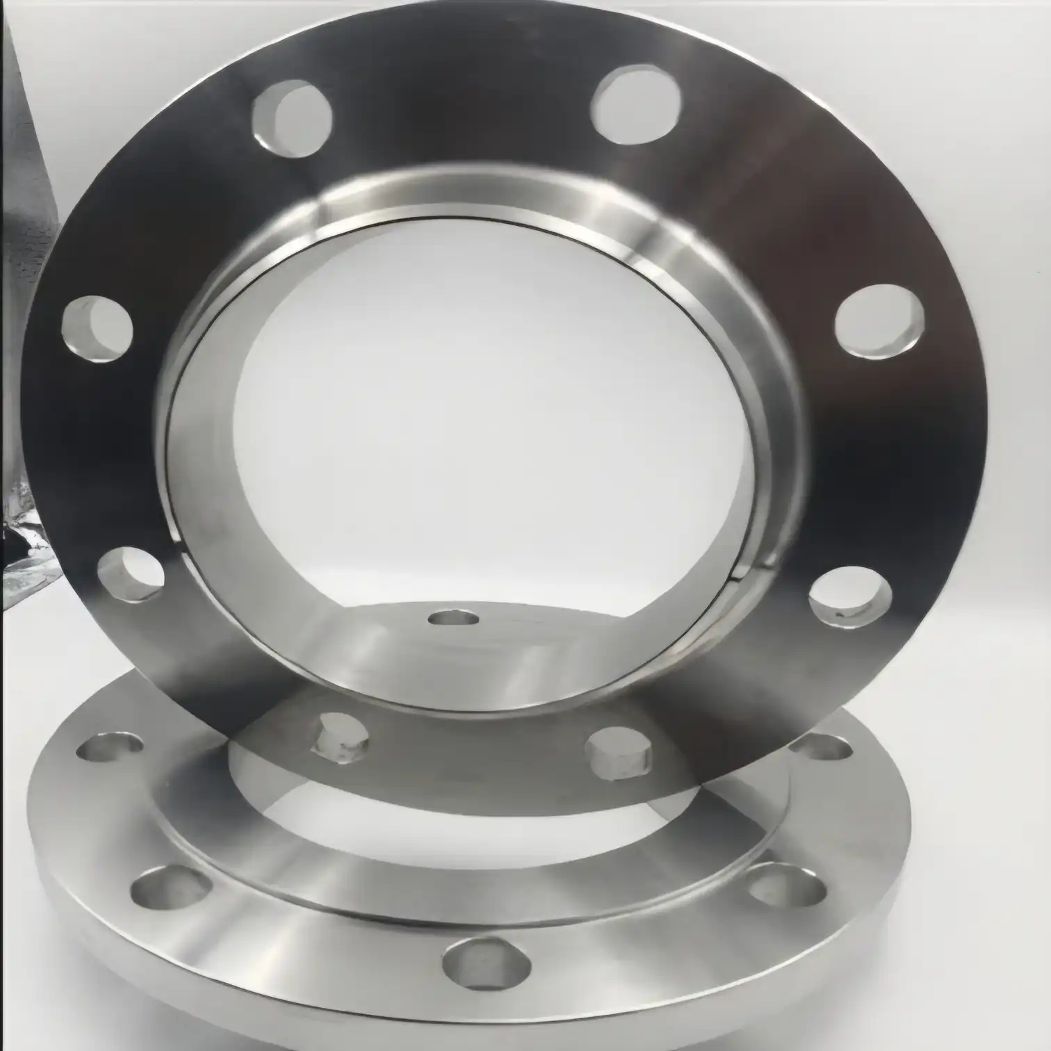
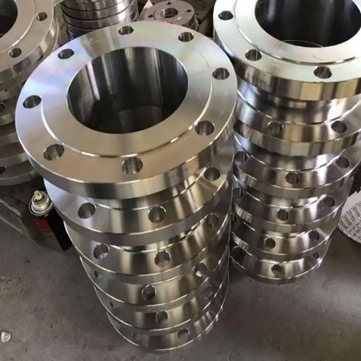
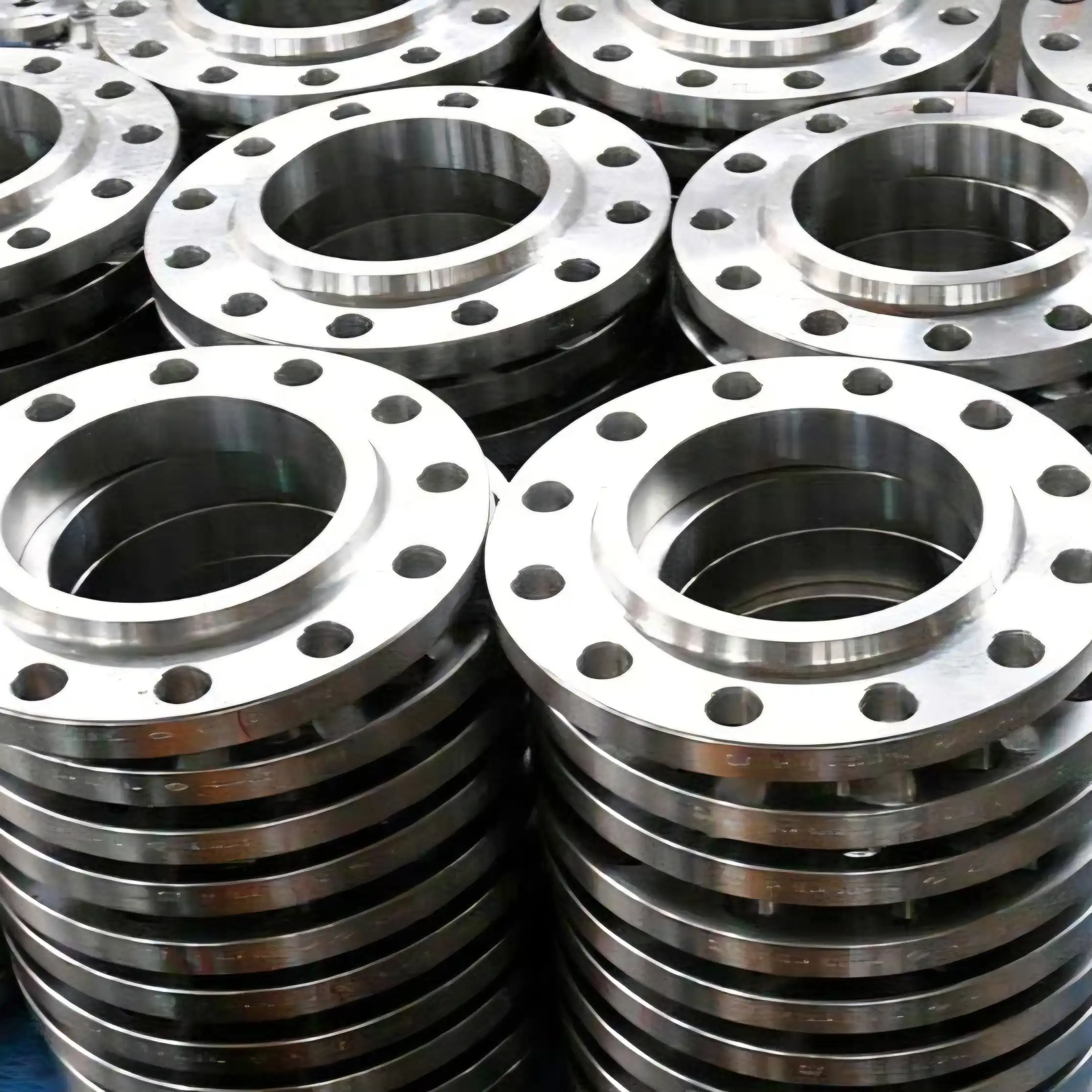
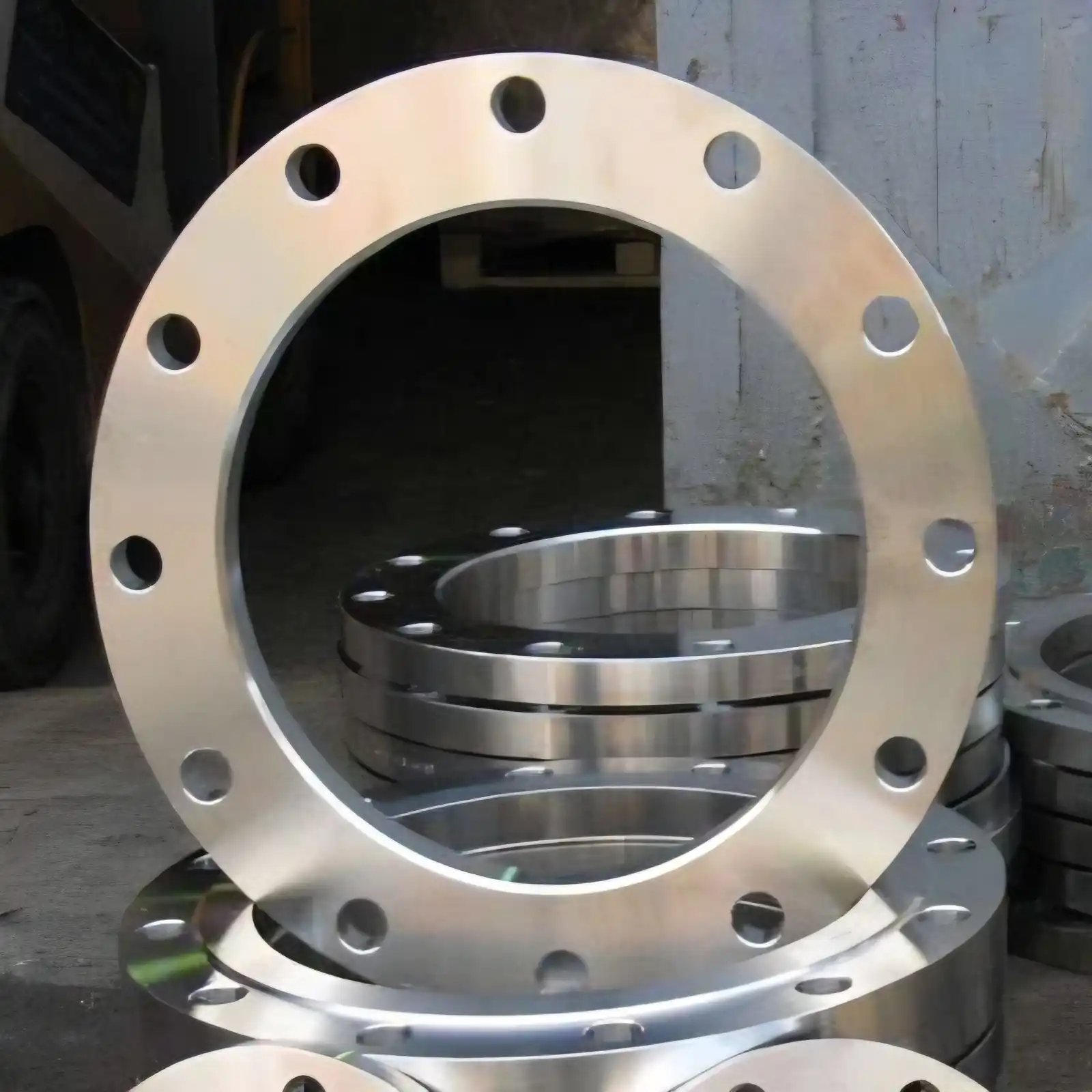
Rubber Bellows with Flange are designed to absorb vibration, thermal expansion, axial movement, lateral deflection and minor misalignment between connected equipment. The flange forms the main bolted connection between the rubber bellows and adjoining pipes, pumps, valves or mechanical equipment, providing secure installation and proper load transfer. Depending on the application, flange configurations may include fixed, loose, rotating, split or integral types. Typical flange specifications include nominal diameter, pressure class, flange thickness, bolt-hole quantity, bolt-hole diameter, PCD and facing type. Flanges may be manufactured from Carbon Steel, Stainless Steel SS304/SS316 or other specified materials according to service requirements.
The flange is essential for ensuring compatibility, sealing, alignment and reliable installation of Rubber Bellows with Flange within a piping system. A correctly selected flange allows the bellows assembly to connect accurately with standard pipe or equipment flanges while maintaining mechanical stability during operation. Technical specifications may follow standards such as ASME B16.5, ASME B16.47, EN 1092-1, DIN or JIS, depending on project requirements. Flange ratings may be specified by ASME Class or PN designation, with options such as Flat Face, Raised Face and Full Face. Material grade, operating pressure, temperature, media compatibility and required bellows movement should also be considered.
Drilling standards of Rubber Bellow flanges
Rubber Bellow flange standards are established dimensional and technical specifications used to define how flanges for rubber bellows are designed, manufactured and connected with piping systems and equipment. These standards ensure compatibility between the rubber bellow flange and its mating pipe, valve, pump or equipment flange by specifying parameters such as nominal size, outside diameter, flange thickness, pitch circle diameter (PCD), bolt-hole arrangement, facing type and pressure rating. ANSI/ASME, AWWA, DIN/EN, PN, BS 10 and JIS are among the commonly referenced flange standards for different industrial, waterworks and international piping applications. Selecting the appropriate standard helps maintain accurate alignment, secure bolting, effective gasket seating and reliable sealing during operation. Details as below :
ANSI : ANSI/ASME B16.5 is commonly used for Rubber Bellow flange connections in industrial piping. Flanges are generally specified by NPS size and pressure class, such as Class 150, 300, 600 and higher, with dimensions covering outside diameter, flange thickness, bolt-circle diameter, bolt-hole quantity and facing. For example, an ANSI Class 150 flange uses standardized bolt-hole patterns and can be supplied with Raised Face (RF), Flat Face (FF) or other applicable facings. The final flange dimensions, pressure-temperature rating and material grade should be selected according to the connected piping system and service conditions.
AWWA : AWWA C207 is primarily used for steel pipe flanges in waterworks and large-diameter water-piping applications. The standard includes Classes B, D, E and F, with working-pressure limits depending on flange class and size. For example, Class D is rated at 175 psi (1,207 kPa) for 4–12 in. sizes and 150 psi (1,034 kPa) above 12 in.; Class E is rated up to 275 psi (1,896 kPa), while Class F is rated up to 300 psi (2,068 kPa). Flange OD, bolt circle, bolt diameter and thickness are defined by size and class.
AWWA / DIN : AWWA and DIN-based flange configurations may be selected for Rubber Bellow assemblies according to the existing waterworks or European piping connection. AWWA C207 provides large-diameter steel flange dimensions and pressure classes, while DIN/EN flange systems are generally designated by DN size and PN pressure rating. Important datasheet parameters include nominal diameter, outside diameter, bore, flange thickness, PCD, number and diameter of bolt holes, facing and pressure designation. The flange drilling must always match the mating pipe or equipment flange; AWWA and DIN drilling patterns should not be assumed interchangeable without dimensional verification.
PN6 : This is a nominal pressure designation of 6 bar (approximately 0.6 MPa) used for lower-pressure piping connections. PN6 Rubber Bellow flanges are commonly selected for water, drainage, HVAC and general utility systems where the connected pipeline is designed for this pressure level. Technical flange data includes DN size, flange outside diameter, PCD, bolt-hole diameter and quantity, flange thickness and facing. For example, published PN6 rubber expansion-joint dimensions show DN25 with 100 mm flange OD, 75 mm bolt circle and four Ø12 mm bolt holes. Actual pressure capability depends on temperature, material and complete assembly design.
PN10 : It represents a nominal pressure designation of 10 bar (1.0 MPa) and is widely used for water, HVAC, utility and general industrial piping. A PN10 Rubber Bellow flange is selected where the mating pipeline and equipment use the same PN10 drilling arrangement. Technical specifications normally include DN/NPS, flange OD, PCD, bolt-hole diameter and quantity, flange thickness and face configuration. For example, PN-series rubber expansion-joint tables specify these dimensions by DN size, allowing the flange to be matched accurately with the pipeline. The actual allowable working pressure must be confirmed against temperature, material and manufacturer design data.
PN16 : It denotes a nominal pressure rating of 16 bar (1.6 MPa) and is commonly specified for higher-pressure water, process, HVAC and industrial piping systems compared with PN6 and PN10 connections. PN16 Rubber Bellow flanges are manufactured according to the required DN size and matching bolt pattern. The technical datasheet can specify flange OD, PCD, number and diameter of bolt holes, flange thickness, bore and facing. Proper matching with the mating PN16 flange is essential for correct gasket seating and bolt alignment. Working pressure should be evaluated together with operating temperature, rubber compound, flange material and movement requirements.
BS 10 : It specifies dimensions for flanges and bolting for pipes, valves and fittings, using Table designations rather than the PN system. Rubber Bellow flange assemblies may therefore be supplied to applicable BS 10 tables such as Table D or Table E, depending on the required connection. Technical data includes nominal bore, flange outside diameter, bolt-circle diameter, number and diameter of bolt holes, flange thickness and bore. The selected table must correspond with the mating BS 10 flange. Pressure capability is dependent on the table, size, material and service conditions, so the applicable design data should be confirmed for each installation.
JIS 5K : This is a Japanese flange pressure designation used for relatively low-pressure piping connections. JIS 5K Rubber Bellow flanges are commonly selected for compatible Japanese-standard water, utility and industrial piping systems. Technical specifications include nominal diameter, flange outside diameter, bolt-circle diameter, bolt-hole size and quantity, flange thickness and raised-face dimensions. For example, published JIS 5K data lists DN100 with 200 mm flange OD, 165 mm bolt circle and eight Ø18 mm bolt holes, with 16 mm flange thickness. Dimensions vary with DN size and must be matched with the mating JIS flange.
JIS 10K : It provides a higher nominal pressure designation than JIS 5K and is used for compatible Japanese-standard piping systems requiring the corresponding flange connection. JIS 10K Rubber Bellow flange specifications include DN size, flange OD, bolt-circle diameter, bolt-hole diameter and quantity, flange thickness and raised-face dimensions. For example, published JIS 10K dimensions for DN100 specify a 210 mm flange OD, 175 mm bolt circle, eight Ø18 mm bolt holes and 18 mm flange thickness. Correct mating-flange compatibility is essential because JIS 5K and JIS 10K drilling dimensions are different.
Flange options are available for Rubber Bellows
Rubber Bellows can be supplied with different flange options to match various piping systems, equipment connections and installation requirements. The appropriate flange configuration depends on factors such as nominal size, pressure rating, operating temperature, movement, media compatibility and connection standard. Depending on the application, fixed, loose, split, integral and Van Stone-type flange arrangements can be considered. Flanges may also be manufactured in Carbon Steel, Stainless Steel, Galvanized Steel and other suitable materials. All details as below :
Fixed flanges : These are permanently attached to the Bellows and provide a rigid connection with the mating pipeline or equipment. They are suitable for applications requiring stable alignment and reliable bolted connections. Dimensions and drilling can be manufactured according to standards such as ASME B16.5, EN 1092-1, DIN or JIS, with pressure classes selected according to system requirements. Common flange materials include Carbon steel and Stainless steel.
Loose or rotating flanges : These can rotate independently around the bellows connection, making bolt-hole alignment easier during installation. This configuration is particularly useful where accurate alignment of fixed bolt holes is difficult. Flange dimensions, PCD, bolt-hole diameter and drilling pattern can be selected to match the mating flange. Depending on the application, specifications can follow ASME B16.5, EN 1092-1 or JIS standards, with suitable material and pressure rating.
Split flanges : This type consist of multiple sections that can be assembled around the Bellows connection. They are useful where installation or replacement requires easier access without extensive dismantling of the connected piping. Split flange designs can be supplied in Carbon steel, Stainless steel or other specified materials. Dimensional requirements, bolt configuration, flange thickness and pressure rating can be customized according to the piping arrangement and applicable standards.
Integral flanges : These are designed as part of the Bellows assembly to provide a compact and mechanically stable connection. They are commonly selected where space limitations, alignment and structural integrity are important considerations. The flange can be designed according to ASME/ANSI, EN, DIN or JIS dimensional requirements, depending on the pipeline system. Important specifications include DN/NPS size, flange thickness, PCD, bolt-hole configuration, facing type and pressure class.
Van stone flanges : This type flanges feature a loose rotating flange arrangement that allows convenient bolt-hole alignment while maintaining the required connection geometry. This design can simplify installation and is useful in systems where flange orientation needs adjustment. Depending on the application, the flange can be manufactured from carbon steel or stainless steel and supplied with Flat Face (FF), Raised Face (RF) or other compatible facing configurations. Dimensions can be matched to recognized piping standards.
Flange materials : Rubber Bellow with flanges are available in materials selected according to operating conditions and corrosion requirements. Carbon Steel is commonly used for general industrial applications, while Stainless Steel grades such as SS304 and SS316/316L can be selected for improved corrosion resistance or demanding media conditions. Material selection should consider the fluid or gas, operating temperature, pressure, environmental exposure and required service life. Material certificates and specific grades can be provided where required.
Flange standards and pressure ratings : Flanges for Rubber Bellows can be manufactured to recognized standards including ASME B16.5, ASME B16.47, EN 1092-1, DIN and JIS, subject to size and application requirements. Key specifications include Nominal Diameter (DN/NPS), Pressure Class or PN Rating, flange thickness, PCD, number and diameter of bolt holes, and facing type. The selected rating should be compatible with the connected piping system and the actual operating pressure and temperature.
Custom flange options : This flange configurations can be developed for Rubber Bellows where standard flange dimensions do not match existing equipment or piping. Customization may include non-standard dimensions, special drilling patterns, bolt-hole arrangements, flange thickness, materials, facing types and connection geometry. The design should consider the required axial, lateral and angular movement of the bellows along with operating pressure and temperature. Engineering drawings and dimensional specifications can be prepared according to project requirements and applicable industry standards.
Flange materials of Rubber Bellows (grades)
ASTM A105 / ASME SA105 – Carbon Steel : ASTM A105 forged carbon steel is commonly used for Rubber Bellows with Flange in general industrial piping, water, air, HVAC, pumps and non-corrosive process services. Typical composition is C ≤0.35%, Mn 0.60–1.05%, Si 0.10–0.35%, P ≤0.035%, S ≤0.040%, Cr ≤0.30%, Ni ≤0.40%, Mo ≤0.12% and V ≤0.08%. It provides good mechanical strength and economical fabrication. Flanges are generally specified to ASME B16.5, with Class 150, 300 or higher ratings depending on design conditions.
ASTM A350 LF2 / ASME SA350 LF2 – Low Temperature Carbon Steel : LF2 is selected for Rubber Bellows flange applications exposed to low operating temperatures, such as outdoor, offshore, LPG and cold-service piping. Typical chemistry includes C ≤0.30%, Mn 0.60–1.35%, Si 0.15–0.30%, P ≤0.035%, S ≤0.040%, Cr ≤0.30%, Ni ≤0.40% and Mo ≤0.12%. The grade is particularly relevant where impact toughness at low temperature is required. Flange pressure class, impact-test requirements and design temperature should be specified in the datasheet.
ASTM A182 F304 / ASME SA182 F304 – Stainless Steel : F304 stainless steel is used for Rubber Bellows flanges where general corrosion resistance, cleanability and durability are required, including food, chemical, water-treatment and process applications. Typical composition is C ≤0.08%, Mn ≤2.00%, Si ≤1.00%, P ≤0.045%, S ≤0.030%, Cr 18–20% and Ni 8–11%. The chromium-nickel austenitic structure provides good resistance to atmospheric and many process environments. Flange dimensions and pressure classes can be specified according to ASME B16.5.
ASTM A182 F304L / ASME SA182 F304L – Low-Carbon Stainless Steel : F304L is preferred for Rubber Bellows flange assemblies where welding is involved and reduced carbon content is desirable. Its typical chemistry includes C ≤0.030%, Mn ≤2.00%, Si ≤1.00%, P ≤0.045%, S ≤0.030%, Cr 18–20% and Ni 8–13%. The low carbon level helps reduce carbide precipitation concerns during welding. It is suitable for process piping, water systems and corrosive environments where 304-level corrosion resistance is adequate. Flange size, Class, thickness and drilling can be specified according to ASME B16.5.
ASTM A182 F316 / ASME SA182 F316 – Stainless Steel : F316 is selected for Rubber Bellows flanges requiring enhanced resistance to pitting and chloride-containing environments. Typical composition includes C ≤0.08%, Mn ≤2.00%, Si ≤1.00%, P ≤0.045%, S ≤0.030%, Cr 16–18%, Ni 10–14% and Mo 2–3%. The addition of molybdenum makes F316 suitable for chemical processing, marine exposure, wastewater and chloride-bearing services. Flanges can be manufactured with ASME B16.5 dimensions and specified pressure classes, facing types and bolt-hole configurations.
ASTM A182 F316L / ASME SA182 F316L – Low-Carbon Stainless Steel : F316L combines the corrosion resistance of 316 stainless steel with a maximum carbon content of approximately 0.030%. Typical composition includes Cr 16–18%, Ni 10–14%, Mo 2–3%, Mn ≤2.00%, Si ≤1.00%, P ≤0.045% and S ≤0.030%. It is particularly useful for welded Rubber Bellows flange assemblies in chemical, pharmaceutical, marine and process applications. The flange datasheet can specify DN/NPS, ASME Class, flange thickness, PCD, bolt-hole quantity, facing and material certification.
ASTM A182 F11 / ASME SA182 F11 – Chromium-Molybdenum Alloy Steel : F11 is used where Rubber Bellows flange components are exposed to elevated-temperature service, particularly steam, thermal-fluid and power-generation systems. Typical chemistry includes C 0.05–0.15%, Mn 0.30–0.60%, Si 0.50–1.00%, Cr 1.00–1.50% and Mo 0.44–0.65%, with controlled P and S. Chromium and molybdenum improve high-temperature strength and resistance to oxidation. Flange pressure-temperature rating, heat-treatment condition and material certification should be defined in the technical datasheet.
ASTM A182 F22 / ASME SA182 F22 – Chromium-Molybdenum Alloy Steel : F22 is intended for demanding high-temperature and high-pressure applications where greater Cr-Mo alloy content is required. Typical chemistry includes C 0.05–0.15%, Mn 0.30–0.60%, Si ≤0.50%, Cr 2.00–2.50%, Mo 0.87–1.13%, P ≤0.025% and S ≤0.025%. It can be used for Rubber Bellows flange connections in power plants, steam systems, refinery equipment and high-temperature process lines. Proper heat treatment and pressure-temperature rating are important design parameters.
ASTM A182 F51 / UNS S31803 – Duplex Stainless Steel : F51 Duplex 2205 is used for Rubber Bellows flange applications requiring both high mechanical strength and strong resistance to chloride-induced corrosion. Typical composition includes C ≤0.030%, Mn ≤2.00%, Si ≤1.00%, Cr 21–23%, Ni 4.5–6.5%, Mo 2.5–3.5%, P ≤0.030%, S ≤0.020% and controlled nitrogen. It is suitable for seawater, offshore, marine, chemical and high-chloride services. Duplex flanges require appropriate solution heat treatment and material certification for the specified grade.
EN 10222-2 P250GH / EN 1092-1 – Pressure-Purpose Steel : P250GH, Material No. 1.0460, is a European pressure-purpose steel used for flange applications involving moderate pressure and temperature. Typical composition includes C 0.18–0.23%, Mn 0.40–0.70%, Si ≤0.40%, P ≤0.025%, S ≤0.015%, Cr ≤0.30%, Ni ≤0.30%, Mo ≤0.08%, Cu ≤0.30%, V ≤0.02% and Al ≥0.020%. It is suitable for steam, process, power and general pressure piping. EN 1092-1 provides the relevant flange dimensional and PN-rating framework.
ASTM B564 / Nickel Alloys – Alloy 625, UNS N06625 : Nickel Alloy 625 can be specified for Rubber Bellows flanges exposed to highly corrosive chemical, marine or aggressive process environments. Typical composition includes Ni as balance, Cr 20–23%, Mo 8–10%, Nb + Ta 3.15–4.15%, Fe ≤5%, C ≤0.10%, Mn ≤0.50% and Si ≤0.50%. Its high nickel, chromium and molybdenum content provides strong corrosion resistance. Because this is a specialized material, flange dimensions, pressure rating, temperature, welding requirements and material certification should be defined project-specifically.
How to select the right flange for Rubber Bellows
Selecting the right flange for rubber bellows requires careful consideration of the piping system, operating conditions and connection requirements. The flange is responsible for creating a secure mechanical connection between the rubber bellows and the adjoining pipe, valve, pump or equipment. Proper selection involves checking nominal size, pressure rating, material, flange standard, facing, drilling pattern, temperature, media compatibility and required bellows movement. Standards such as ASME B16.5, EN 1092-1, JIS B 2220 and BS 10 may be used depending on the piping system. The complete flange specification should be verified against the mating flange and the manufacturer’s technical datasheet before final selection. Details as below :
Determine the nominal flange size : The flange size should correspond to the nominal pipe size and the connection dimensions of the rubber bellows. Common sizes may be specified as DN50, DN100, DN150 or NPS 2, NPS 4 and NPS 6. The flange bore should be compatible with the bellows opening and connected piping to avoid restriction or installation problems. For industrial piping, dimensional requirements may be selected according to ASME B16.5, while European systems may use EN 1092-1 and Japanese systems JIS B 2220. The datasheet should specify DN/NPS, outside diameter, bore, PCD and flange thickness for accurate dimensional matching.
Select the required pressure rating : The flange pressure rating must be suitable for the design pressure and operating temperature of the piping system. Common specifications include ASME Class 150, Class 300, PN6, PN10, PN16, JIS 5K and JIS 10K. Pressure capability is influenced by flange material and temperature, so the nominal rating should not be treated as the actual allowable working pressure under every condition. The Rubber Bellows itself must also have a compatible pressure rating. Technical selection should therefore consider design pressure, maximum operating temperature, pressure fluctuations and the applicable pressure-temperature requirements of the selected flange standard.
Choose the flange material : Flange material should be selected according to corrosion conditions, operating temperature, fluid characteristics and mechanical requirements. Carbon steel such as ASTM A105 is commonly used for general industrial water, air and utility services. Stainless steel grades such as ASTM A182 F304, F304L, F316 and F316L are suitable for applications requiring higher corrosion resistance. Alloy steel, duplex stainless steel and other materials may be selected for specialized services. The technical datasheet should identify the exact material grade, applicable ASTM or EN specification, heat-treatment condition where relevant, and material certification requirements for the Rubber Bellows flange.
Match the flange standard : The selected flange must conform to the dimensional standard used by the connected piping system. ASME B16.5 is widely used for industrial flanges by NPS size and pressure class, while EN 1092-1 uses DN and PN designations. JIS B 2220 is used for Japanese-standard flange dimensions, and BS 10 provides table-based flange dimensions. Waterworks applications may use AWWA C207. Before selecting the Rubber Bellows flange, the manufacturer should verify the exact standard, size, pressure designation, flange thickness, bolt circle and drilling pattern. Mixing standards without dimensional verification can lead to bolt misalignment and improper installation.
Select the correct flange facing : Flange facing must be compatible with the mating flange and gasket arrangement. Common facing configurations include Flat Face, Raised Face and Full Face, depending on the selected standard and application. Facing dimensions and surface requirements can affect gasket seating and sealing performance. For a Rubber Bellows assembly, the flange face should provide adequate support without interfering with the rubber body or movement zone. The technical specification should identify the facing type, nominal size, pressure class, gasket arrangement and applicable standard. Proper face matching is particularly important where leakage prevention, vibration resistance and repeated maintenance are significant considerations.
Verify the bolt-hole configuration : Correct bolt-hole drilling is essential for accurate installation of a Rubber Bellows flange. The technical datasheet should specify the number of bolt holes, bolt-hole diameter, pitch circle diameter, hole spacing and bolt specification. These dimensions vary between ASME, EN, JIS, BS and AWWA flange standards. For example, two flanges having the same nominal diameter may have different drilling patterns when manufactured to different standards. The flange should therefore be checked against the actual mating pipe or equipment flange before fabrication. Correct drilling ensures proper bolt alignment, uniform gasket compression and secure connection during operation.
Consider operating temperature and fluid compatibility : Flange selection must be evaluated together with the operating temperature and the medium conveyed through the piping system. The flange material should retain suitable mechanical properties at the minimum and maximum design temperatures, while the rubber bellows compound must remain compatible with the fluid. Water, air, oil, fuel, chemicals and corrosive process media may require different material combinations. The specification should include design temperature, operating temperature, fluid type, concentration where applicable and corrosion environment. Material selections such as ASTM A105, A182 F304L or F316L should be verified against the complete service conditions and project requirements.
Check bellows movement and installation requirements : The flange arrangement should support the required movement of the rubber bellows without creating excessive mechanical stress. Axial movement, lateral displacement, angular movement, vibration and thermal expansion should be considered when selecting fixed, loose, rotating, split or other flange configurations. Installation space and accessibility may also influence the flange design. The datasheet should identify allowable axial compression or extension, lateral movement, angular deflection, flange dimensions and connection details. Proper pipe alignment and suitable support are equally important because a flange should not be used to compensate for excessive pipeline misalignment beyond the manufacturer’s specified movement capability.
Confirm the complete technical datasheet : Before finalizing a Rubber Bellows flange, all selected parameters should be consolidated into a technical datasheet for dimensional and functional verification. Essential information includes flange standard, DN/NPS, pressure rating, material grade, flange thickness, outside diameter, bore, PCD, bolt-hole quantity and diameter, facing type, operating pressure, design temperature and bellows movement. The datasheet should also identify rubber compound, connection type, gasket requirements and applicable manufacturing standards. Final approval should confirm compatibility with the mating flange and piping specification. This systematic approach reduces installation errors, improves sealing reliability and supports dependable long-term service of the complete Rubber Bellows assembly.
Rubber Bellows with Loose flange and Fixed flange
Rubber Bellows with Loose flange and Fixed flange are two common flange configurations used to connect flexible rubber expansion joints with pipes, pumps, valves and other equipment. Both provide a bolted connection, but their flange arrangement, installation method and alignment characteristics differ. A loose flange can rotate independently around the bellows connection, making bolt-hole alignment easier, while a fixed flange maintains a permanent orientation with the bellows. Selection depends on piping layout, pressure rating, installation space, maintenance requirements and required movement. Typical specifications may include DN/NPS, ASME Class or PN rating, flange material, PCD, bolt-hole dimensions and facing type. Details as follows :
Difference between loose and fixed flanges : The fundamental difference is the flange’s relationship with the rubber bellows assembly. A loose flange is free to rotate around the connection, allowing its bolt holes to be positioned correctly against the mating flange during installation. A fixed flange is permanently attached or rigidly positioned, so its bolt-hole orientation is predetermined. Both configurations can be manufactured according to standards such as ASME B16.5, EN 1092-1 or JIS B 2220. Loose flanges generally offer greater installation flexibility, while fixed flanges provide a more rigid and permanently oriented connection for the piping system.
When to choose a loose flange : Loose flanges are selected when installation flexibility and easy bolt-hole alignment are important. They are particularly useful where the mating pipe or equipment flange has a fixed orientation and cannot easily be rotated. The flange can be positioned rotationally before the bolts are tightened, simplifying field installation and maintenance. Loose flange Rubber Bellows are commonly considered for water pipelines, HVAC systems, pump connections and utility piping. Typical specifications include DN50–DN600 or larger, PN10/PN16 or ASME Class 150 ratings, depending on design, with Carbon Steel or Stainless Steel flange materials and FF or RF facing configurations.
When to choose a fixed flange : Fixed flanges are selected where a rigid and permanently oriented connection is required. They are commonly used on pump nozzles, valve connections, industrial process piping and equipment where the flange orientation is predetermined. A fixed flange maintains its position relative to the bellows and provides a stable bolted connection. Depending on the application, specifications may include ASME B16.5 Class 150 or Class 300, EN 1092-1 PN10 or PN16, or JIS B 2220 10K. Material options can include ASTM A105 carbon steel, ASTM A182 F304/F316 stainless steel and other project-specified grades.
Where loose flanges are used : Loose flange Rubber Bellows are frequently used where installation and maintenance access are significant considerations. Typical applications include chilled-water systems, cooling-water pipelines, HVAC networks, water-treatment plants, pump suction and discharge connections and general utility piping. Their rotational capability helps compensate for flange-hole orientation during assembly but does not mean the bellows should be used to correct excessive pipe misalignment. Technical specifications should include nominal diameter, pressure rating, flange material, PCD, bolt-hole quantity and diameter, flange thickness and facing. The complete assembly should be rated according to the manufacturer’s pressure, temperature and movement limitations.
Where fixed flanges are used : Fixed flange Rubber Bellows are commonly selected for applications where the connection requires a predetermined orientation and greater structural rigidity. They can be used in industrial process lines, pump and valve connections, machinery nozzles, steam-related auxiliary systems and other equipment connections. The flange remains fixed relative to the bellows, so accurate pipeline alignment is important before installation. Technical specifications may include DN/NPS size, ASME Class 150/300, PN16 or JIS 10K rating, flange thickness, PCD, bolt-hole dimensions and RF or FF facing. Material selection should be based on pressure, temperature, corrosion and process-media requirements.
Loose flange specification : A loose flange is designed around the bellows connection so that the flange can rotate for easier alignment. Its datasheet may specify DN/NPS, outside diameter, bore, PCD, bolt-hole diameter, number of holes, flange thickness, material and facing. Common material choices include ASTM A105, ASTM A182 F304L and F316L. Depending on the piping system, dimensions can follow ASME B16.5, EN 1092-1 or JIS B 2220. Pressure designations may include PN10, PN16, Class 150 or JIS 10K. The actual allowable pressure and movement must be confirmed from the complete Rubber Bellows manufacturer’s technical data.
Fixed flange specification : Rubber Bellows Fixed flange specifications are based on the applicable piping standard, nominal size, pressure class and connection geometry. Typical datasheet information includes flange outside diameter, bore, thickness, PCD, bolt-hole quantity and diameter, facing and material grade. ASTM A105 carbon steel and ASTM A182 F304/F316 stainless steel are common material options for industrial applications. Dimensions may conform to ASME B16.5, EN 1092-1 or JIS B 2220. Because the flange orientation is fixed, bolt-hole positioning and pipeline alignment must be established accurately during fabrication and installation. The complete assembly rating must consider pressure, temperature and bellows movement.
Pressure, temperature and movement considerations : Neither loose nor fixed flange selection should be made independently of the rubber bellows design. The complete assembly must accommodate the specified operating pressure, temperature and movement requirements. Important movement parameters include axial compression or extension, lateral displacement and angular deflection. Pressure designations such as PN10, PN16, ASME Class 150 or Class 300 describe the flange connection system, but the Rubber Bellows may have a different allowable working pressure depending on its construction and rubber compound. The technical datasheet should therefore state pressure, temperature, movement limits, flange standard and material together for correct selection.
Flange and bellows compatibility : The flange must be compatible with the rubber bellows connection, mating pipeline and installation method. Flange material, dimensions, pressure rating and facing should be selected together with the rubber compound and reinforcement design. For example, a stainless-steel flange may be preferred where corrosion resistance is required, while ASTM A105 carbon steel may be suitable for general water or utility services. The mating flange must have the same applicable drilling arrangement, including PCD, bolt-hole diameter and quantity. Proper compatibility ensures correct gasket seating, uniform bolting and reliable sealing while allowing the Rubber Bellows to perform its intended movement and vibration-isolation function.